 |
||||||||
6.2
Design of Condenser
The condenser/ evaporator must be designed in such a way that the
ammonia vapor, when condensed, can be stored in it. Therefore, the volume of
the condenser/evaporator must be at least 2.5 liters, which is the quantity of
ammonia required to convert 5 liters of water into ice.
The dimensions of the inner tank. Which holds ice, is as follows:
Length = 24.5 cm
Breath = 25 cm
Height = 8 cm
Considering allowance, the height of tank is 12 cm
The volume of the condenser is
Vc = p/4 [4d2 b lb + 6 d2c
lc + 16d2v lv]
Where
|
db |
= = |
Inside dia.
Of the pipe of the bottom frame f
5.08 cm |
|
dc |
= = |
Inside dia.
of the cross pipes f
1.27 cm |
|
dv |
= = |
Inside dia
of the vertical pipes f
1.27 cm |
|
lc |
= = |
Length of
each cross pipe 25 cm |
|
Lv |
= = |
Length of
each vertical pipe 8 cm |
Vc = p/4 [4
( 5.08)2 (32) + 6(1.27)2 (25) + 16(1.27)2 (8) ]
= 2946.5 cm3
= 2.95 liters
Since the volume of the condenser is more than the volume of condensed ammonia required, the design is safe
6.3
Insulation
Thickness
of thermocol = 45 mm
(at the
top and bottom)
thickness
of glass wool = 85 mm
(At the
sides)
7.1. Flat Plate Collector:
(a) Collector Tubes and Header:
Two G.I tubes, one of which is f 5.08 cm
and the other f10.16 cm,
and length 112 cm were taken. Twelve holes were drilled on each pipe to
accommodate the end of the collector tubes of f1.27 cm. The G.I pipes of f 5.08 cm forms the lower header and that of f 10.16 cm
forms the upper header. These two
headers were connected by G.I pipes of f 1.27 cm. The ends of f 1.27 cm pipes were gas-welded with the headers. The upper
header was provided with two f 1.27 cm
pipes, one for charging of aqua-ammonia solution and the other for carrying
ammonia vapour to the condenser. The lower header was provided with one f 1.27 cm
pipe for the return line.
(b) Absorber plate:
The absorber plate was made from a
24-gauge aluminium sheet. The sheet was corrugated so as to accommodate the 12
G>I tubes of 1.27 cm. This was accomplished by carving a semi-circular
groove on a wooden block over which the aluminium sheet was placed on the
aluminium sheet over the groove . the rod was then hammered along the length
until the sheet was corrugated to the required shape . this was done at ten
desired positions along the width of the sheet ,the pitch being maintained at
10 cm.
Dimensions
of the absorber plate
|
Length |
= |
121.92
cm |
|
Width |
= |
91.44 cm |
|
Area |
= |
1.115 m2 |
Holes were
punched by the side of the grooves to facilitate the collector plate to be tied
to the tubes.
The
absorber plate was then placed on to the tubes such that the grooves covered
the ten tubes , leaving out one tube at each side to facilitate convection
.wires were then passed through the holes and around the tubes and the absorber
plate. Black board paint was then applied to the upper surface of the plate.
This type of contact between the absorber plate and the collector tubes ensures a god bond and heat transfer. However, the air gap small it may be, will itself form insulation and hence, decrease in plate efficiency is inevitable. Also, if the bond is good, all the heat is collected by the plate should be transferred to the working medium only through this small contact. This turns out to be a very inefficient method. However, soldered bond is expensive and heating and cooling of the pipes may result in cracks being developed at the joints.
(c) Collector case:
The collector case was made of plywood of size
143.2cm x
120cm x 20.32cm. The bottom was covered with plywood board of size 143.2cm x
120cm. The top was covered with a glass plate and frame, which was hinged to
one of the longer sides.
The collector tubes and absorber plate
assembly was placed in this case after packing the case with a layer of glass
wool of 8cm. Thickness. As mentioned earlier, only 10 pipes were covered with
the absorber plate, leaving out one at each side. These two pipes were also
insulated with glass wool, so that they do not get heated. This facilitates the
convection current to be set up inside the collector tubes, so that the
aqua-ammonia solution gets heated and ammonia is liberated.
Glass cover with frame:
Ordinary window glass of size
110cm x 110cm x 0.3cm was used. This glass cover was placed at a distance of
8cm above the absorber plate.
Shalimar tar-wax was applied to the top edges of the case to
form a layer of 0.3cm thickness and 0.6cm width. When the frame rests on the
edge, an air tight seal is obtained at the place of contact. It also acts as a
cushion to the glass plate.
Orientation of the collector:
The collector assembly was placed with an angle of tilt of
300 and facing south. The collector was turned at an angle of 80
towards west to take advantage of the afternoon sun.
7.2 Condenser
The condenser was made from G.I.
pipes of f1.27cm, f2.54cm and
f
5.08cm.firstly,two square frames of pipes were made, one from f2.24cm
pipe and the other from f5.08cm
pipe. Each pipe was cut into four pieces of required length at an angle of 450
to the axis of the pipe. The ends were then welded to form a square frame. The
lower frame was made from f5.08cm
pipe and the upper frame from f2.54cm
pipe.
The next step was to connect the
square frames together. For this, sixteen holes were drilled on each frame and
facing each other so as to accommodate the ends of sixteen f1.27cm
pipes were gas welded on to the square frames after positioning them properly
in the holes.
Six G.I pipes of f1.27cm
gas-welded to the two opposite pipes of the lower frame, which were provided
with the required size holes.
Two f1.27cm G.I. pipes were used as the inlet and outlet for
ammonia vapour, and were gas-welded on to the top of the frame.
A tank was made from G.I sheet, such that it fitted inside the
condenser. The dimensions of the tank are
|
Length |
: |
24.5cm |
|
Breath |
: |
25cm |
|
Height |
: |
12cm |
Water, which is to be cooled to
form ice, is to be filled only to height of 8cm so that the volume is 5 liters.
Stagnant water jacket:
If stagnant water is used for
cooling the condenser, then large quantity of water is required for efficient
condensation. A separate tank has to be provided for this purpose. So, a tank
of G.I> sheet was made to the following dimensions.
|
Length |
= |
43.2cm |
|
Breath |
= |
43.2cm |
|
Height |
= |
22.8cm |
A lid was provided at the top to
facilitate the insertion and removal of the inner tank. The top of the tank was
covered with thermocol and the sides were insulated by glass wool. The whole
set up was enclosed in a box made of hard board of 6mm thickness.
Structures
Structures were provided to hold
the collector and condenser in place. The condenser was placed at a higher
level with respect to the collector to prevent the aqua–ammonia solution from
getting into the condenser.
Connecting Pipes
The collector and condenser were
connected by means of f 1.27 cm
G.I. pipes. The outlet from the upper header of collector was connected to the
inlet of the condenser via a 1.2m. Rectifying column made from 1.27 cm G.I
pipe. The outlet of the condenser was connected to the inlet of the lower
header of the collector.
Valves
Stop values made of cast iron body
and steel ball valve inside were provided to regulate the flow of ammonia from
the collector to the condenser and back.
8
Instrumentation
Thermometers were used to measure
a. The
temperature of the absorber plate
b. The
temperature of the condenser
c. The
ambient temperature
8.2 Experimental Procedure
The apparatus was made leak proof
by applying shellac at the pipe joints. It was then charged with aqua–ammonia
solution and the charging valve was closed.
The temperature of the absorber
plate was measured and recorded and corresponding ambient temperature were
noted.
During nighttime, refrigeration
took place. The temperature of the condenser was noted in the morning the next
day. The readings were then tabulated.
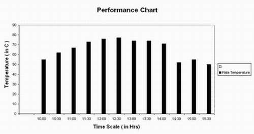
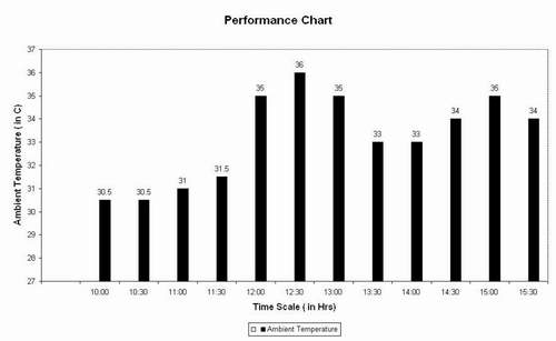
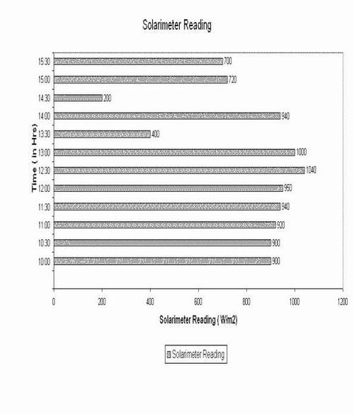
RESULTS
PERFORMANCE
TEST
Date:
-------------
|
TIME |
PLATE TEMPERATURE IN 0C |
AMBIENT TEMPERATURE IN 0C |
SOLARIMETER READING IN W/m2 |
|
|
|
|
|
|
10–00 AM |
55.0 |
30.5 |
900 |
|
10–30 AM |
62.0 |
30.5 |
900 |
|
11–00 AM |
67.0 |
31.0 |
920 |
|
11–30 AM |
73.0 |
31.5 |
940 |
|
12–00 AM |
76.0 |
35.0 |
950 |
|
12–30 AM |
77.0 |
36.0 |
1040 |
|
01–00 AM |
74.0 |
35.0 |
1000 |
|
01–30 AM |
74.0 |
33.0 |
400 |
|
02–00 AM |
71.0 |
33.0 |
940 |
|
02–30 AM |
52.0 |
34.0 |
200 |
|
03–00 AM |
55.0 |
35.0 |
720 |
|
03–30 AM |
50.0 |
34.0 |
700 |
At 6.00 pm water was filled in the
inner tank of the condenser at 280C.
At 12.30 am the temperature of
water was 240C.
At 6.30 am the temperature of
water was 200C.
This unit can be used in rural
areas where electricity is not available. This unit is simple to operate.
The unit was designed to produce
ice. However, we were able to get only chilled water.
The coat of the set–up is very
high. If solar refrigerators can be made on large scale, the cost of each unit
can be effectively reduced and used economically in rural areas.
SUGGESTION FOR IMPROVENT
Some improvement have been
proposed, but I was not applied due to technical difficulties, shortage of time
and non–availability of materials and equipments. These are as follows:
1. Double glazing can be used
instead of single glazing, so that the heat loss can be reduced and hence
efficiency can be increased.
2. Mirrors can be used to
concentrate the solar radiation on the absorber plate.
3. the air from the set–up must be
removed prior to charging.
4. A drain valve must be provided
between the condenser– evaporator and generator – absorber o drain out the
condensed water.
5. An array of the plate
collectors can be used tp increase the collector area.
10.
ECONIMIC ANALYSIS
COLLECTOR
|
4” GI pipes 1.1 meters |
|
|
|
|
2” GI pipes 1.1 meters |
|
|
|
|
½” GI pipes 20 meters |
|
|
|
|
Glass plate (1.1 x1.1 meters ) x0.3 mm thick |
|
|
|
|
Aluminium sheet(4’ x 3’) |
|
|
|
|
Black board paint(200 ml) |
|
|
|
|
Wooden planks |
|
|
|
|
Labour for wooden box |
|
|
|
|
Labour and gas welding material |
|
|
|
|
Paint(green) |
|
|
|
|
Steel wires,hinges,latches etc. |
|
|
|
|
Valves (4 in number)1/2” inch |
|
|
|
|
Cardboard |
|
|
|
|
Aqua–ammonia solution (10
liters) |
|
|
|
|
CONDENSER |
|
|
|
|
2” GI pipes 4”6’ |
|
|
|
|
1” GI pipes 4”8’ |
|
|
|
|
½” GI pipes 8” |
|
|
|
|
Gas welding material and labour |
|
|
|
|
Thermocol |
|
|
|
|
GI sheet and labour charge for
condenser tank |
|
|
|
|
Card board condenser box |
|
|
|
|
Fevicol |
|
|
|
|
Hinges, latches and screws |
|
|
|
|
Wooden stripes (1/2” x
1/2") |
|
|
|
|
Labour for card board box |
|
|
|
|
Drilling of holes |
|
|
|
|
|
|
|
|
|
Structures
for collector and condenser |
|
|
|
|
900 angle plates to
collector ( 11 m) |
|
|
|
|
900 angle plates for
ondenser |
|
|
|
|
¾” ms rod (21 kg) |
|
|
|
|
2” x ¼” MS flat bar (15 kg) |
|
|
|
|
PROJECT REPORT (-------------) |
|
|
|
|
OTHER CHARGES |
|
|
|
|
Elbows |
|
|
|
|
Wooden planks Painting charges |
|
|
|
|
Traveling charges |
|
|
|
|
Miscellaneous |
|
|
|
|
Arc welding rods |
|
|
|
|
Synopsis charge |
|
|
|
|
GARND TOTAL: |
|
|
|
|
|
|
|
|
|
|
|
|
|
|
|
|
|
|
11.
TARGET APPLICATION

For vaccine
storage and medical uses:
The World
Health Organization’s Global Programme for Vaccines and Immunization and its Expanded Programme on Immunization/EPI
has approved a number of low voltage DC PV vaccine refrigerators. Solar vaccine
refrigerators are designed specifically to meet health needs, and are not
appropriate for private use (e.g., refrigerating food and drink).
Technology
Availability:
The WHO has certified a number of models from
companies in the world for their GPV/EPI programmes. PV fridges and freezers
are generally only available on order from source manufacturers.
Fuel/Energy
Availability:
Most areas in the tropics have
sufficient solar energy availability for PV vaccine refrigeration systems.
Individual systems may have to be designed based on particular needs of the
clinic or health Programme.
Optimum
Situation:
Off-grid rural health clinics and hospitals with more than 4 kWh/m2/day solar radiation. Note that there must be sufficient technical infrastructure and manpower in place to service, monitor, and maintain the fridges. In cases where infrastructure is insufficient, consider LPG or kerosene fridges.
REFERENCES
|
SR NO |
INDUSTRY |
ADDRESS |
||
|
1 |
Jade
Mountain Inc http://www.jademountain.com |
P.O. Box 4616, Boulder, CO
80306 US |
||
|
2 |
Small
Power Systems |
74550
Dobie Lane |
||
|
|
|
|
||
|
|
BOOKS |
AUTHOR |
||
|
1 |
Refrigerator Handbook |
Operation and Maintenance
Manual, Whirlpool |
||
|
2 |
Guide to Insulations |
Dupont |
||
|
3 |
Solar Energy 5(1),(1961) ; Solar Energy 6(4), (1962) |
Prof. J.C.V. Chinnappa
|
||
|
|
|
|
||
|
4 |
Refrigeration and Air
Conditioning |
Domkhundwar |
||
|
|
||||
|
|
CASE STUDY |
AUTHOR |
||
|
|
|
|
||
|
1 |
Creating
a Renewable Energy Future |
Keith
Lee Kozloff and Roger C. Dower |
||
|
2 |
Bringing
Power to the People |
Daniel
M. Kammen |
||
|
3 |
Energy
Needs in Developing Countries and Sustainability |
José
Goldemberg |
||
| PAGE 3 | |||||||||
2002©Arma Technologies, all rights reserved disclaimer & copyright
If you find any of your copyrighted content email us the same along with proper proof ,the requisite material will be removed within a week