
|
||||||||
4.
METHODOLOGY
Our aim is to develop a non-electric
solar refrigerator-freezer. The refrigerator uses an aqua-ammonia absorption
system similar to that used in propane refrigerators. The refrigerator consists
of two separate units; the solar collector-generator and the refrigerator box.
The collector-generator
consists of a thermal solar collector and most of the refrigeration works. It
needs to be mounted in a sunny location, the same as any solar collector.
The refrigerator
box is the refrigerator per se and can be placed wherever is convenient, presumably
the kitchen.When the sun shines, the collector-generator produces ammonia refrigerant,
which is stored until night when the actual cooling takes place. To keep the
refrigerator cold through the day and during cloudy weather, there is built-in
storage. There are no moving parts.
In use, our
solar refrigerator is little different from any other refrigerator. Currently,
the drawbacks are a greater temperature variation since there is only one cycle
per day.
We are also
studying a very small unit where the refrigerator box is under the solar collector
so it is all one unit that is left outside. This is meant to be used for vaccines
and to be as low cost and simple as possible. We intend to include a freezer
for a limited ice-making capacity, as this simplifies the design.
We have been
looking seriously at auxiliary cooling for prolonged cloudy spells. We are trying
an external heat pipe for colder locations and thermoelectric cooling for warmer
locations. These have the advantage of being relatively inexpensive and can
be offered as add-ons instead of requiring extensive redesigning.
The other
technology, which can be implemented, is keeping the cold storage outside at
the solar collector and using a pump to circulate the cold into the refrigerator.
This would add significantly to the expense and require electricity, but would
simplify installation and keep ammonia out of the living space.
.
5.Absorption
refrigeration using solar energy
Refrigeration
is gaining very much importance in todays world. But the refrigeration that
we see us uses electricity-powered generation.
In some places
electricity is not readily available and also it is becoming costlier, so we
have to go for non-conventional type of refrigeration. Solar powered refrigeration
is useful where sunshine is in abundance in countries like India.
5.1 Components:
The main components of solar refrigerator
using intermittent absorption cycle are as follows. (Ref Fig 5.1.1)
The flat
plate collector acts as a generator during daytime and as absorber during night.
It consists of an upper header and a lower header of GI material and the two
headers connected by means of a number of collector tubes in between.
Ammonia
water solution is placed inside this system. During the daytime, ammonia gets
evaporated from the solution by absorbing solar energy. During nighttime, ammonia
vapor is absorbed back in the weak solution.
During the
day time ammonia vapor gets collected and condensed in the condenser evaporator.
During nighttime the condensed ammonia absorbs heat from the system to be cooled,
vaporizes and returns to the collector.
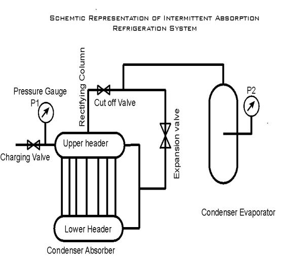
There are
totally three valves in the system one valve is in the charging line, second
valve line is between upper header and the condenser. The third valve is in
the vapor return line.
5.2 Working of the system
The generator
is charged with pre-generated amount of water and ammonia to give the required
concentration of ammonia in the solution. At the commencement of the refrigeration
period the line is opened between the upper header and the condenser, at the
end of regeneration period, the condenser is isolated from the rest of the system
and the generator absorber is allowed to cool. To carry out refrigeration the
valve between the evaporator and the collector is opened.
So
the ammonia liquid in the evaporator absorbs the heat from the water to be cooled,
gets evaporated and this vapor returns to the collector where it is absorbed
again. This cycle is repeated again the next day.
As this process of evaporation continues,
the temperature of water gets reduced and thus refrigeration is achieved.
5.3
WORKING FLUID
(REFRIGERANT)
5.3.1 Definition:
Any substance that absorbs heat through expansion or vaporization may be called a refrigerant. A broader definition may include such secondary cooling media as brine solution and cold water.
5.3.2 Requirements for a refrigerant:
These are certain desirable characteristics
which a fluid used as a refrigerant should possess.
1)
It should be non-poisonous
2)
It should be non-explosive
3)
Condensing pressure should not be excessive
4)
Low boiling temperature at atmospheric pressure
5)
High critical temperature
6)
High latent heat of vaporization
7)
Low specific heat of liquid
8)
Low specific volume of vapor
9)
It should be non-corrosive
10)
Chemically stable
11)
Ease of locating leaks
12)
Availability, low cost and ease of handling
13)
Satisfactory heat transfer and viscosity coefficients
14)
Freezing temperature of the liquid should be below any temperature
at which the evaporator might operate
15) Low compressor discharge temperatures are desirable
5.3.3
Classification of refrigerants:
The National Refrigeration Society Code,
U.S.A., catalogues all the refrigerants into three groups.
These are:
Group-One :( safest of refrigerants).
R-113, R-611,
R-11, R-21, R-114, R-12,
R-30, R-22,
R-744, R-502, R-13, R-14, R-500.
Group-Two : ( toxic and somewhat flammable
refrigerants).
R-1130, R-611,
R-160, R-764, R-40, R-717.
Group-Three :( flammable refrigerants)
R-600, R-601,
R-290, R-170, R-1150, R-50.
We used ammonia as the refrigerant.
Ammonia comes under group two refrigerants and is denoted by R-717. It was one
of the first refrigerants used.
It is used in large industrial installations. It is
colorless. Its boiling temperature at atmospheric pressure is 33.8C and the
melting point from the solid is 77.8C.It is somewhat flammable and forms an
explosive mixture with air. It attacks bronze in the presence of a little moisture
but does not corrode iron and steel. This refrigerant is extremely soluble in
water.
Ammonia leaks can be easily detected by smell
or by burning Sulphur candles or wicks, which generate a dense cloud of white
smoke in the presence of ammonia vapor.
6. THERMODYNAMIC ANALYSIS
1)
Amount of ice to be produced is 5 kg
2)
Refrigerant used is ammonia
(NH3)
3)
Absorbent used is water
(H2O)
4)
Average ambient temperature at Davangere.
During day time = 320C
During night time =
270C
5)
Amount of heat to be removed from water to convert it into
ice
Q
= mS ( ta tb) + mL
Where
M
= Mass of ice to be produced
= 5 kg
SW = Secific
heat of water = 4.187 kJ/ kg k
TA = Ambient
temperature =
+320C = 3050k
TB = Temperature
of ice =
100C = 2630K
L
= Latent heat of water
at 0oC
= 335 kJ/kg
Q
= 5 [ 4.187(305 273)
+ 2.0935 (273 263) + 335 ]
Q
= 12449.535
= 2450 kJ/kg
This is the heat load or refrigerator effect. Considering heat
flow through insulation let the heat load be equal to 2450 kJ.
(6) Condenser temperature,
tc = 400C
(7) Evaporater temperature,
te =
100C
(8) Enthalpy
of ammonia fluid at condenser temperature
h =
390.587 kJ/kg
(9) Enthalpy of vapor
ammonia at evaporator temperature
= hg =
1450.22 kJ/kg
(10)
Refrigerating effect,
Qe
= hg hf
=
145.22 390.587
= 1059.63
kJ/kg
This refrigerating effect is to be obtained
in 12 hours. Therefore, heat removed,
Qe = 2450 /
( 12 x
3600)
= 0.0567 kJ/S
(11) Let ma
be the mass of ammonia required
Qe = ma qe
Therefore,
ma = Qe/qe
= 0.0567/1059.53
= 5.35 x 105 x 12 x 3600
= 2.312 kg
This is the
mass of ammonia required to obtain the refrigerating effect for 12 hours, let it be 2.5 kg.
(12) Calculation of coefficient of performance
of refrigeration (COP)
T2 ( T3 T1)
[COP] = ---------------------------
T3
(T1 T2)
Where
T1 = Condenser temperature
= 400C = 3130k
T2 = Evaporater
temperature = 100C = 2630C
T3 = Generator temperature
= 700C
= 3430k
263 ( 343 313 )
[COP] = ------------------------------
= 0.46
343( 313 263 )
Hence co-efficient of performance
pf the system
[COP] =
0.46
6.1
Design of Flat Plate Collector
Volume and area calculations:
i) area of the corrugated sheet
= length x breath
= ( 95 x 94 ) cm2
= 8930 cm2 = 0.8930
m2
ii) volume of the upper header
length, l = 1.1 m = 110 cm
diameter,d =
4 = 10.16 cm
volume
= pd2/4 x l = p x (10.16)2/4 x 110
= 8918.05 cm3
= 8.91805 liters
iii) volume of the lower header
length ,l
= 1.1 m = 110 cm
diameter.d = 2 = 5.08 cm
volume
= pd2/4 x l
= p(5.08)2/(4)
x 110
= 2229.5 cm3
= 2.23 liters
iv) volume of the connecting pipes
length of each pipe = 112 cm
diameter of each pipe = 1.27 cm
number of pipes = 12 nos
volume
= pd2/4
x l x12
= p (1.27)2/4 x 112 x 12
= 1702.5 cm3 = 1.702
liters
v) volume of the collector
= volume of upper header + volume
of lower
header + volume of connecting pipes
= 8.918 + 2.23
+ 1.702
= 12.85 liters
CALCULATIONS F PLAE EFFICIENCY FACTOR AND OVERALL COLLECTOR EFFICIENCY:
CALCULATIONS:
(1) to find the overall heat loss coefficient,
UL
U
= Ut + Ub
Ut
= top loss coeffient
Ub
= back loss coeffient
Where
Ut
= [ (l/hpc + hrpc)
+ (l/hw + hrcs)]1
Where
hpc = Heat tranfer coefficient
from plate to cover
(glass)
hrpc = radiation
heat tranfer coefficient from plate to
cover plate
hw = heat tranfer coefficient of wind blowing over
collector
hrcs
= radiation heat transfer coeffient from cover (glass) to sky
hpc =
[(1 0.0018) (T-10)] x 1.14 dt0.31] 0.070
T = average temperature between plate and cover
dt = difference in temperature between plate and
cover
l = distance between plate and cover
hrpc = g
( T2p + T2c) (Tp + Tc)
(l/Ep) + (l/Ec)
1
Tp = plate yemperature in 0K
Tc = cover glass temperature in K
Ep = plate emittance
Ec = cover emittance
g = Stefan boltzman constant
h = Ec g (T2c + T2s)2
(Tc + Ts)
Tc = cover glass temperature
Ts = sky glass temperature + ambient temperature
hw = 5.7 +
3.8 (V)
V = velocity of wind blowing over collector
TO FIND THE HEAT LOSS COEFFICIENT, UL
Plate-to-cover spacing
= 8 cm
= l
Plate emittance
= 0.821
= Ep
Ambient air + sky temperature
= 320C = Ts
Wind speed
= 5m/sec
= v
(from wind mill data)
back insulation thickness
= 10cm
insulation conductivity = 0.065 w/m-0C
mean plate temperature =
900C
(assumed)
Ub
= K/L
= 0.065/8 x 102
= 0.8125
W/m2-0C
Ut = [(l/hpc + hrps)
+ (l/hw + hrcs)]1
Hpc = [l0.0018
(T 10)] x 1.14 dt0.310
l0.070
T = 45 + 90/2
= 67.5 0C
dt = 90 45
= 45 0C
L = 8 cms
hpc =
[( l 0.0018 x (67.5 10)] x 1.14
x (45)0.31/(8)0.07
= [ l 0.0018 (57.5)] x 1.14 x 3.25/1.15
= 2.88 W/m20C
hrpc = (T2p + T2c) (Tp + Tc)
(1/Ep) + (1/Ec) 1
= 4.87
x 108 [(90+ 73)2+(45+273)2] [(90+273)+(45+273)]
1/0.821
+ 1/0.837 1
= 6.33 W/m20C
hrcs = Ec g (T2c
+ T2s) (tc + ts)
= 0.837 x 4.87 x 108 (3182
+ 3052 ) (318 + 305)
= 5.73 W/m20C
hw
= 5.7 +
3.8 (V)
= 5.7 +
3.8 (5)
= 24.7
Ut = [1/(hpc
+hrps) + 1/(hs + hrcs)]
hpc = 2.88
W/m2
hrpc = 6.33
W/m2
hw
= 24.7 W/m2
hrcs = 5.73
W/m2
Ut
= [1/2.88 + 6.33) + 1/(24.7 + 5.73)] 1
= 7.074 W/m20C
Bottom layer coefficient, Ub:
Ub
= K/L
K
= thermal conductivity of insulation
(Glass wool)
= 0.056
~Kcal/m2hr0C
= 0.056/0.86
= 0.065W/m0C
L
= insulation thickness = 8
cm
Ub = 0.035/8 x 102
= 0.8125
UL = Ut + Ub
= 7.07 + 0.8125
= 7.9
II PLATE
EFFICIENCY FACTOR, Fp:
I WUL WUL WUL W
= + + +
Fp pdh pdk/m Cb
b + 2bF
Kp
= thermal conductivity of plate material
= 59.86
W/m0C
W = pitch =
0.1 m
|
UL |
= |
Collector heat loss co-efficient = 7.9 w/m2 |
|
D |
= |
Dia of the pipe = 1.27 cm =0.0127 |
|
H |
= |
Average heat transfer coefficient of fluid to tube wall = 68.86 w/m2 |
|
K |
= |
Length extension coefficient = 44.986 W/m 0C |
|
Cb |
= |
Air bond conductance between collector Plate and Tube =27.68 W/m0C |
|
A2 |
= |
UL 7.90 ----- = ---------------------- = 268.43 KpM 58.859 x 0.0005
|
|
A |
= |
16.38 |
|
b
b |
= = = |
W B/2 0.1 0.0177/2 0.04115 m |
|
Ab |
= = |
16.38 x .04115 0.0674 m |
|
F |
= |
Tanh (ab) tanh( 0.674 ) ------------ = ------------------- = 0.871 ab 0.674 |
|
WUL ------- pdh |
= |
0.1 x 7.9 ---------------------------------------- = 0.2875 p x 12.7 x 103 x 68.86 |
|
WUL ------- pdk/m |
= |
0.1 x 7.9 ----------------------------------------------------- p x 12.7 x 103 x 44.986/0.005
|
|
|
= |
0.0022 |
|
WUL ---------------- Cb
|
=
= |
0.1 x 7.9 ---------------------------- = .0285 27.683 0.0285 |
| W ------------------ b + 2bF |
=
= |
0.1 ----------------------------------------- 0.0177 + 2 x 0.04115 x 0.871
1.12 |
|
I --------- Fp
|
= |
WUL WUL WUL W ------- + -------- + --------- + ---------------- pdh pdk/m Cb b + 2bF
|
|
|
= |
0.2875 + 0.0022 + 0.0285 + 1.12 |
|
Fp |
= = |
1/1.43 0.6953 |
PLATE EFFICIENCY
FACTOR. Fp = 69.53 %
QUANTITY OF
AQUA AMMONIA USED
Since the volume of the collector
is 12.85 liter, the quantity of ammonia solution to be used is about 12 liters.
| PAGE 2 | END | ||||||||
2002©Arma Technologies, all rights reserved disclaimer & copyright
If you find any of your copyrighted content email us the same along with proper proof ,the requisite material will be removed within a week